ASSEMBLING INSTRUCTION
Earth Fault and Short Circuit Indicator Type EKL4
 (Panel instrument)
Descrition
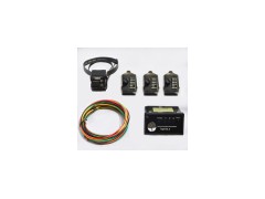
The earth fault and shot circuit indicator consists of:
l 1 pc reading instrument (panel instrument)
l 3 pcs sensors for detecting short circuit current
l 4 pcs linght cable
l 1 pc sensor for observing the sum current
l 1 pc flashing lamp (optional)
Installation of the reading instrument
The Earth Fault and Short Circuit Indicator is designed for panel installation .The necessary dimensions of the cutout are 91.5+0,6x44.5+0,6mm ( refer to figure 2 ) .Before sliding in the instrument , the electrical connections can be accomplished .The housing is slded into the opening and pushed with a light pressure up to stop position .Springs ( figure l ) serve to keep the reading instrument in its position .
Installation of the light cable
 The sensor which is installed on the cable,is connected to
the reading instrument via light cable.Therefore the sensor
of core L 1has to be connected with the terminal L1 on the
back of the reading instrument.(The endings of the light
cables have to be pushed into the pick-up openings up to
stop position.)The same has to be done with the Sensors L2,
L3 and the earth fault sensor 14(figure 3).
Power supply
The power supply is performed via a 3.6 V lithium

battery.For exchanging the battery,a screw cap
on the front side of the indication housing must
be removed by turning it left.The battery must be
taken out and replaced by a new one.(With the
supply via lithium battery,the 230 VAC are only
connected in case the erath fault and short circuit
indicator type EK shall be reset also via recovering
voltage of the net.)
Electric connection
Depending one the version,the electrical connection has to be done according to the designations in figure 3.
Terminals without any marking(NC)are without any function.In principle,the information indicated on the reading instrument is valid.
Setting the display time
The time of displaying after a short circuit or earth is
adjustable.
 There are three times to choose.The standard reste times are:1-2
-4h(other values are possible).The adjustment of the reset times
will be done by a rotaryswitch.The rotary switche is on the front
side of the indicator in the left top corner.The possible switch
positions are shown if figure 4.
Setting the operating points for short circuit
The adjustment of the operating points of the earth fault and shore circuit indicator indicator type EKL4 is done at the sensors.Three different operating points can be adjusted.The operating points are adjusted with a rotary switch at the front side of the sensor.The adjustable operating points are indicated on the front side of the sensor.


